1) How to create piping plan from CADWorx model? (Ground floor, at elevation 4m, 8m & 12m like this)
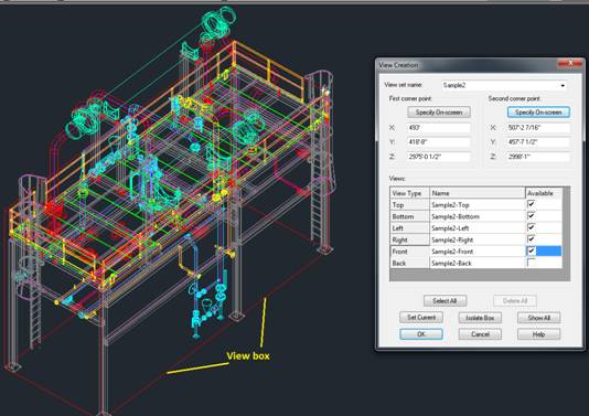
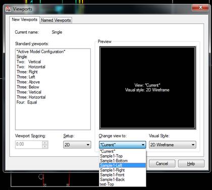
2D plan and elevations are generated using the viewbox command in CADWorx. Generally viewbox are created according to your required level and these clips are recreated in the paper space using viewport command. Thus we can slice the entire 3d model in any plane by defining the coordinates in the ” view creation ” window as shown below. Since we create the 2D drawing in the paperspace, any future modifications/revisions updated in the 3d model will be automatically reflected in the 2d drawing.
Use command – Viewbox , This create view box at the required elevation in modelspace.
Use command – Viewport, to define the required view in the paperspace.
2) How we can generate different elevation views from model?
Same as above.
3) In isometric drawing how we can remove weight column?
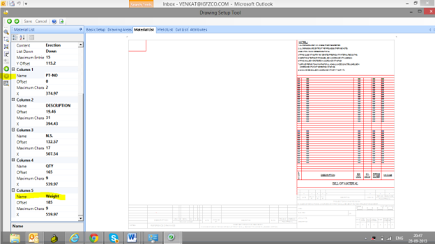
Weight column can be removed form .MLD file if ISOGEN Project settings.
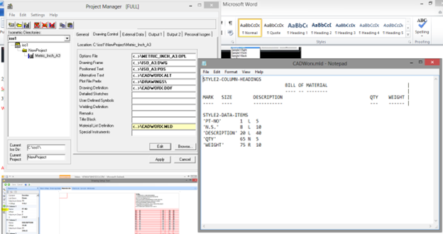
Alternatively you can use iconfigure application and Run Drawing Setup Tool from Wizard Menu.
4) How we can put half coupling during modelling? (For threaded as well as socket weld half coupling)
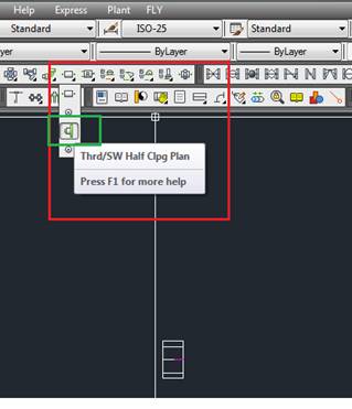
Please use drop down from full coupling icon. Make sure that half coupling is available in the piping spec and also allowed in the Branch table
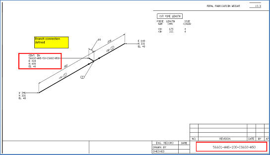
5) If we have line no. 56601-XXX-100-CS602-H50 & from this line we have branch line no. 56602-XXX-50-CS602-H50, at branch connection we are not getting branch/header line no. in isometric generation drawing. How we can get it? (Cross reference line no. is not reflected in isometric drawings)
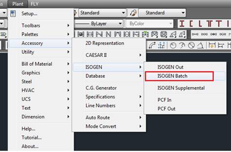
Please use ISOGEN Batch to get the continuation reference.
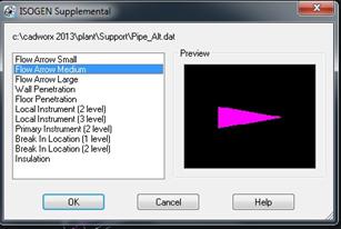
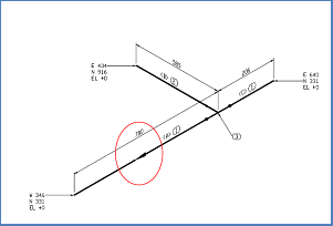
6) Flow direction is not properly coming in isometric drawing. (Not visible in isometric drawing)
Use command ISOGENSUPL.
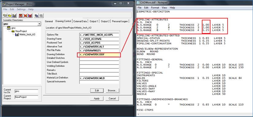
7) How to reduce the line weight of main line in isometric drawing?
Pipeline weights can be customized in the DDF file in Isogen project manager.
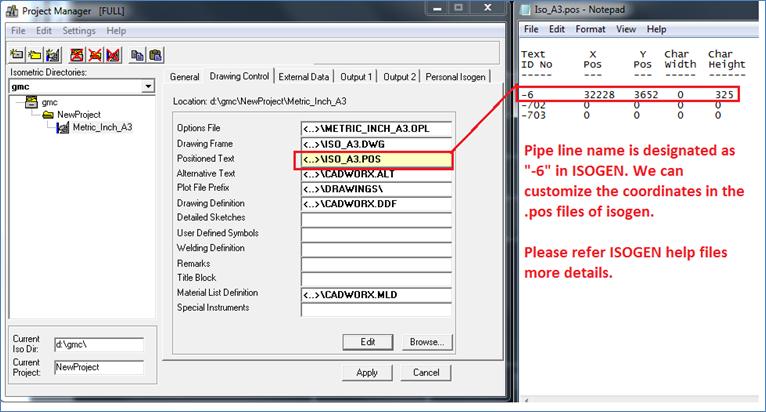
8) During isogeneration Line number is coming on block right up. How we can put at our desired position?
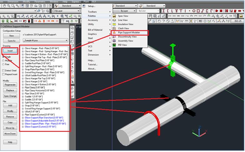
9) How we can put different types of pipe supports (shoe support, guide support, anchor support, u-bolt) in model & how we can customize our support directory as per our requirement? (Supports are not proper visible in isometric drawing)
Pipe support can be modeled using pipe support modeler.
